Building a smart lamp part I: Power consumption and light control
It's more than two years since I started contemplating the idea of creating a cubical smart lamp with the ability to react to touch input. With a relatively high power consumption, building this lamp ended up being more challenging than planned. In this post I will describe some of the problems I had related to the power consumption and control of my lamp.
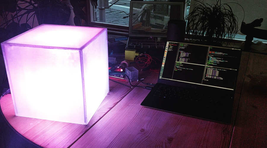
I started constructing the lamp in May 2015. The lamp, which I named Lampe after the Norwegian word for lamp, is a cube shaped box made of matte transparent plexi-glass with each side being an individually controllable light. Each side has a 3W RGB-LED with the ability to show 16 million different colors. The top side of the cube has a thin copper net giving the surface touch sensitive capabilities. Embedded on the circuit board is a microphone for beat detection and a WiFi-chip for wireless communication. The whole system is controlled with a Arduino Nano.
The first iteration
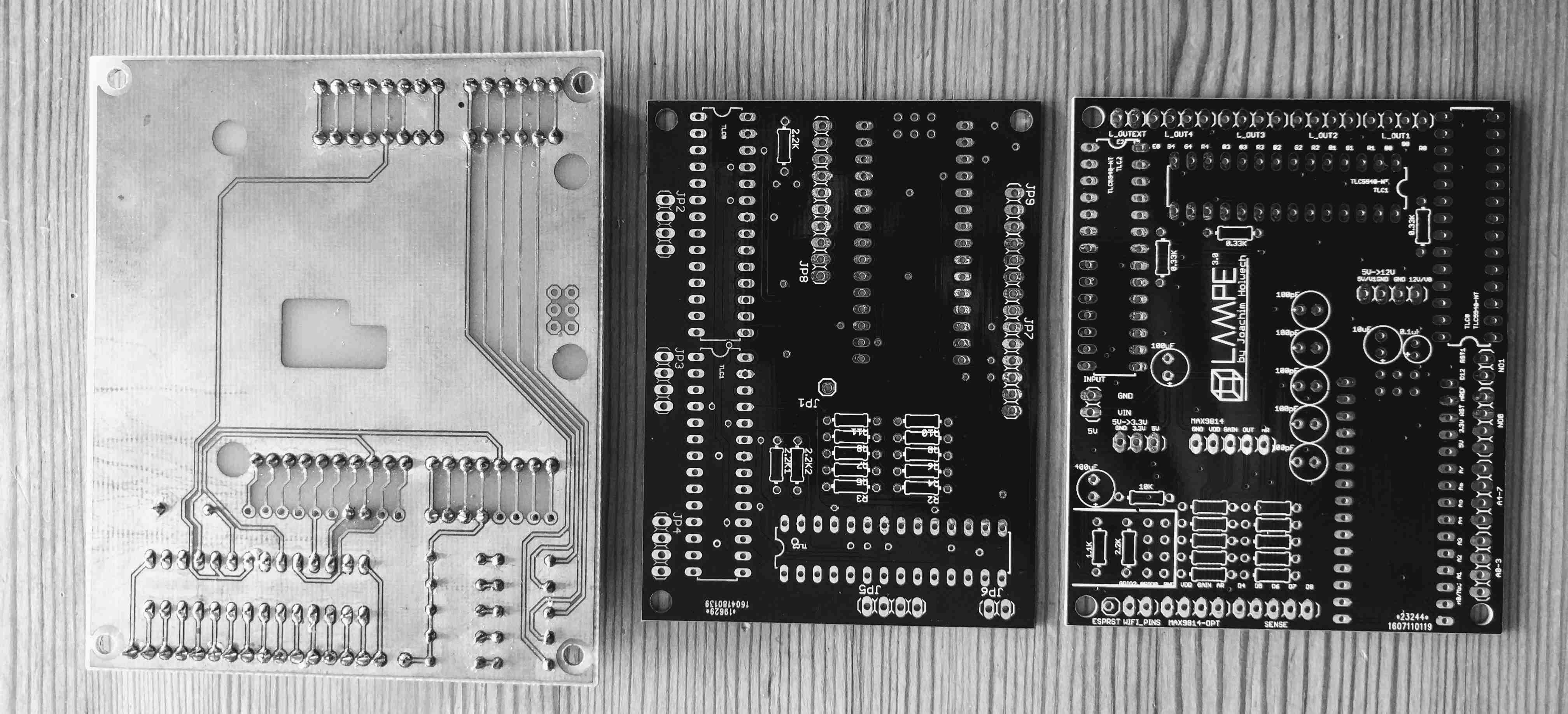
After some planning, I started the construction of the first prototype PCB. With the help of the local electronics enthusiast club at my university, I created the board by hand using the printing tools they had available at the workshop. The board was designed using Eagle, a popular free PCB design tool, a tool I was pretty unfamiliar with at the time. This first board is shown on the left in fig. 1. Sadly and not so surprisingly, things didn’t work out as planned. A problem I would keep running into, was the crazy amount of current the LEDs required. Each individual color requires up to 350mA, which means that the lamp would draw at least 5.25A. Handling high currents was not something I was very familiar with and had never been a topic in any of the electrical engineering classes I had attended, so I was stumped on what to do. This was by far the biggest challenge I had with this project, as low voltage developer boards like the Arduino are not able to handle currents in this range.
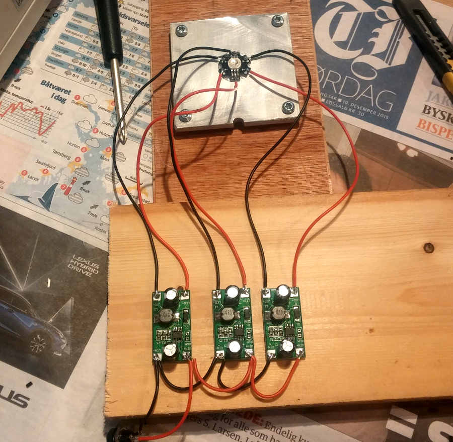
The solution I ended up with, was to use these small 350mA PWM LED drivers. I would have to have one driver for each color, and since I had 5 lights with 3 colors each, that would mean that I needed to have 15 drivers. Not optimal, as it would take up a lot of space but it would fit inside the box. So, I bought some drivers and started testing them. They were handling the current well, and the PWM dimming was working almost as good as I hoped. But a problem appeared when the lights were dimmed to a duty cycle less than 20%. Doing this would cause the lights to start flickering. This was unacceptable as smooth transitions between the different colors is essential for many of the animations I planned on creating. I suspect that the drivers had a poor response time, so that they were not able fully turn on and off at low duty cycle. But I never really managed to figure out what the problem was. I guess that’s the price you pay, for not… paying, and rather buying cheap components on eBay.
Scrapping the board and making a new one
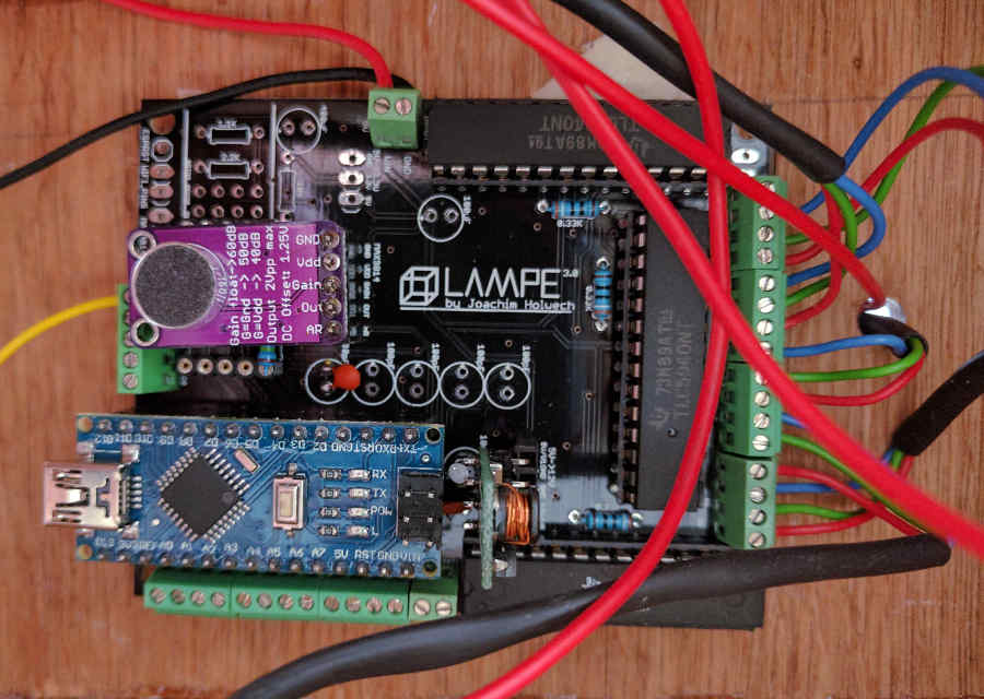
I decided to design a new circuit board as the first one wasn’t made to handle the currents I wanted to use it for. I found an awesome LED driver that would fit my project much better. The TLC5940 is a very compact LED driver made by Texas Instruments. It has 16 outputs, each with a maximum current of 120mA. This driver works well with Arduino boards as there are many libraries that support it on the Arduino platform (I use this library, but I recommend to use FastLED as it is probably the best LED-driver library for Arduino). By combining 3 and 3 outputs I could get 360mA, which is close enough to 350mA. With 3 TLC5940s (3 outputs per color * 3 colors * 5 LEDs = 45 required outputs) all the LEDs could be run directly from the board!
Improving from the previous design iteration, I decided to make the design more compact to save money and space. The board was produced through dirtyPCBs, who make very cheap prototype boards for $11-16. This second board design never ended up being used though, as there was a circuit error rendering it useless. Additionally I decided wanted more functionality like WiFi and a microphone.
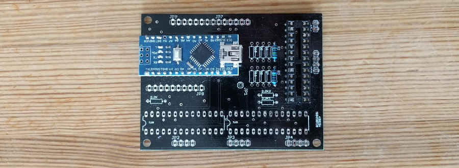
Third time’s a charm
On my last iteration I had finally learned the most important part of PCB-design: Making cool logos. No, but a cool logo and some nice silk-screen does give off a more professional look and that logo is pretty darn awesome! I added capacitors all over the board to compensate for sudden changes in power consumption. This can be a problem for example if one or more lights quickly turn on. Since there is often a delay in the power source, you can get voltage drops in the circuit while waiting for the power source to react to the sudden change. If the voltage sinks too low, weird things can happen with the components and the micro controller could even reset it self. The capacitors hold on to some energy which can be discharged in these situations to compensate for the voltage drop. Additionally, capacitors can remove some noise in the circuit if the right capacitance is selected.
Anyways, that’s a short intro to some of my problems regarding power consumption and control. I will definitely write more about this project, but to keep things short I will stop here. Got questions? Send me an e-mail! And finally, here is a short clip of Lampe doing some blinking: